


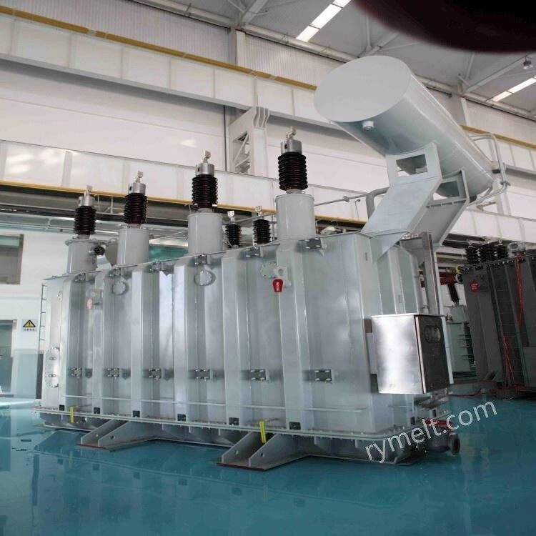
Core Principle
Identical to step-up transformers, based on the law of electromagnetic induction and the turns ratio relationship. The only difference lies in the winding configuration:

Primary Functions and Roles:
Core of Power Distribution: At the end of transmission grids (e.g., substations), step-down transformers reduce high voltage (e.g., 110kV, 35kV) to medium voltage (e.g., 10kV) in stages. Distribution transformers then further reduce this to low voltage (e.g., 400V/230V) suitable for direct user consumption.
Electrical Safety Assurance: Provides safe, standardized voltage levels for industrial, commercial, and residential electricity, ensuring the secure operation of electrical equipment.
Electrical Isolation: Provides electrical separation between primary and secondary circuits, enhancing system safety and immunity to interference.
Equipment Power Adaptation: Supplies specific operating voltages required by machinery, electronic devices, control systems, and similar equipment.

Wider Application Scenarios:
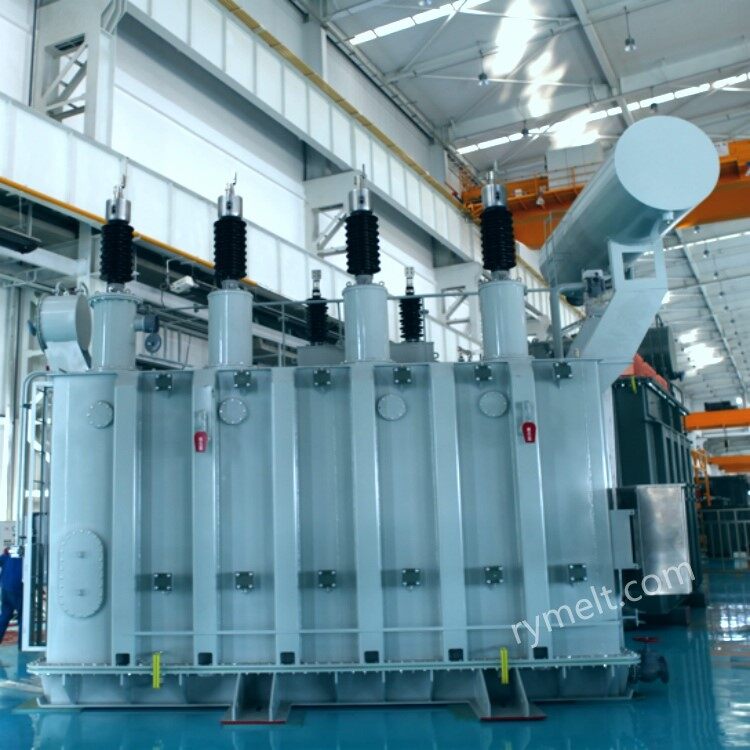
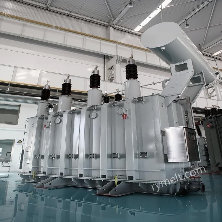
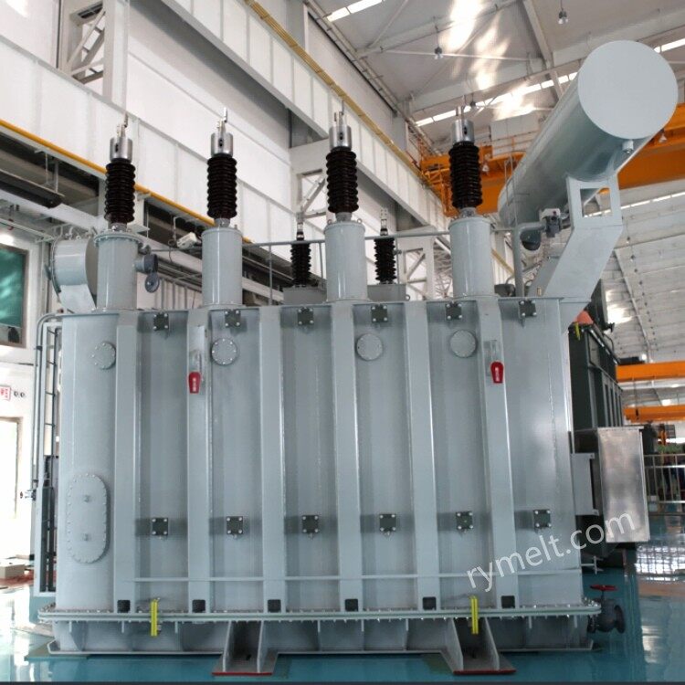
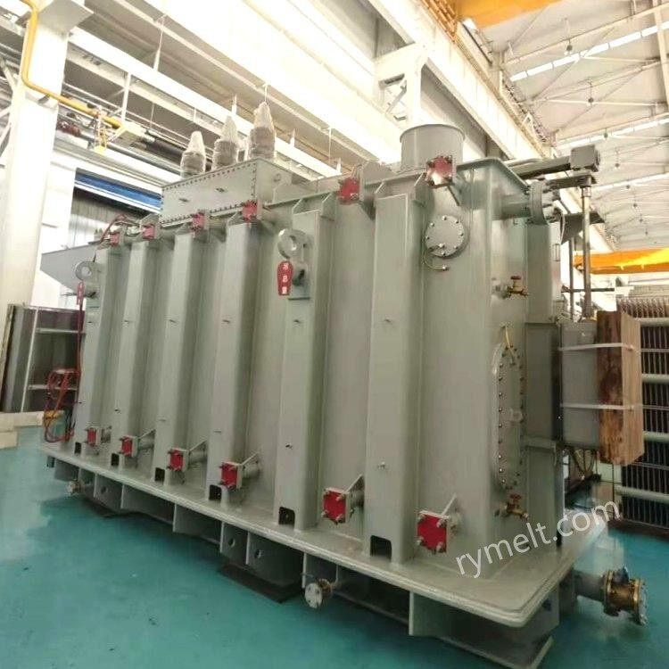
Oil-immersed Transformers: Commonly used in outdoor substations.
Dry-type Transformers: Widely deployed in indoor, building, subway, and data center environments due to fire resistance, environmental friendliness, and simplified maintenance.
Prefabricated Substations (Compact Substation): Compact distribution units integrating step-down transformers, high-voltage switches, and low-voltage distribution equipment.
Winding Characteristics: The high-voltage side (input) features more turns and finer wires; the low-voltage side (output) has fewer turns and thicker wires to accommodate high-current output.

Core Comparison Between Step-Up Transformers and Step-Down Transformers
| Feature | step-up transformer | step-down transformer |
| Core Functionality | Increase the voltage and reduce the current to lower the transmission loss over long distances. | Reduce the voltage and increase the current to safely adapt to terminal electrical equipment. |
| Purpose | Power generation side/transmission end (power plant step-up substation, transmission line hub) | Distribution side/electricity consumption end (substations at all levels, end-user access points) |
| Structural concerns | The insulation level of the high-voltage winding is required to be extremely high, and the heat dissipation design faces great challenges. | The low-voltage winding has a large current and thick wires; more attention is paid to various installation forms (dry-type, box-type transformer). |
| Focus of parameters | Pay more attention to ultra-high voltage insulation, large capacity, and low total loss. | Pay more attention to voltage regulation rate, energy efficiency level (no-load loss), connection group, and noise. |
| Typical connectome | Mostly Yd or Yy to meet the requirements of high-voltage systems. | Low-voltage distribution systems are almost uniformly Dyn11. |
Our transformer factory is equipped with advanced craftsmanship, rigorous quality control measures, and strict factory inspection procedures. Our radiators and components undergo installation and testing under conditions that simulate the on-site operation at the customer's location, effectively ensuring the elimination of leakage points. All flange surfaces are precision-machined, featuring grooved and limiting structures, and high-quality nitrile rubber gaskets that are oil-resistant, weather-resistant, and ozone-resistant are used to prevent transformer leakage. In addition, when handling the bolted connections between the upper and lower sections of the oil tank, a weld-sealed tank edge structure can be adopted according to customer needs, ensuring that the company's products consistently maintain low partial discharge, low noise, low loss, and high reliability

Our company's step-down transformer model S11-10000/110 reference parameters
| Parameter Item | Parameter Value |
| Frequency | 50 Hz |
| Input Voltage | 110 kV |
| Output Voltage | 10.5 kV |
| Phase | Three |
| Model Number | S11-10000/110 |
| Coil Number | 3 |
| Type | Oil-Immersed Transformer |
| Application | POWER SUPPLY |
| Rated Capacity | 10 MVA |
| Standard | IEC60076/GB |
| Vector Group | Yd11/YNd11 |
| Cooling Method | ONAN |
| Material | Copper Winding |
| Winding Material | COPPER |
| Rated Voltage | 110 kV |
| Secondary Voltage | 10.5 kV |
| Tap Changing Method | Off-Load |
Our company's step-down transformer model SFZ18-350000/220 reference parameters
| Parameter Item | Parameter Value |
| Frequency | 50 Hz |
| Input Voltage | 230 kV |
| Output Voltage | 37 kV |
| Phase | Three |
| Coil Number | Two Windings |
| Coil Structure | continuous type |
| Type | Oil-Immersed Transformer |
| Application | Power Transformer |
| Product name | Oil-immersed Power Transformer |
| Rated capacity | 350 MVA |
| Cooling Method | ONAN ONAF |
| Usage | Outdoor Power Line Operation |
| Standard | GB1094 GB/T 6451 |
| Warranty | 12 Months |
| Vector group | Yd11/YNd11 |
| Rated voltage | 220 kV |
| Winding Material | Copper 100% |
| Material | Silicon Steel Sheet |
Our company's dry-type distribution transformer model SCB11-800/10/0.4 reference parameters
| Parameter Item | Parameter Value |
| Frequency | 50 Hz |
| Input Voltage | 10 kV |
| Output Voltage | 400 V |
| Phase | Three |
| Coil Number | 3 |
| Application | POWER SUPPLY |
| Rated Capacity | 800 KVA |
| Vector Group | Dyn11 / Yyn0 |
| Cooling Method | ONAN |
| Material | Copper Winding |
| Winding Material | COPPER |
| Rated Voltage | 10 kV |
| Secondary Voltage | 0.4 kV |
| Tap Changing Method | On-Load |


